


A Class A AIS unit broadcasts the following information every 2 to 10 seconds while underway, and every 3 minutes while at anchor at a power level of 12.5 watts.
| Parameter | Bits | Description |
|---|---|---|
| Message ID | 6 | Identifier for this message 1, 2 or 3 |
| Repeat indicator | 2 | Used by the repeater to indicate how many times a message has been repeated. See Section 4.6.1, Annex 2; 0-3; 0 = default; 3 = do not repeat any more. |
| User ID | 30 | MMSI number |
| Navigational status | 4 | 0 = under way using engine, 1 = at anchor, 2 = not under command, 3 = restricted maneuverability, 4 = constrained by her draught, 5 = moored, 6 = aground, 7 = engaged in fishing, 8 = under way sailing, 9 = reserved for future amendment of navigational status for ships carrying DG, HS, or MP, or IMO hazard or pollutant category C, high speed craft (HSC), 10 = reserved for future amendment of navigational status for ships carrying dangerous goods (DG), harmful substances (HS) or marine pollutants (MP), or IMO hazard or pollutant category A, wing in ground (WIG); 11 = power-driven vessel towing astern (regional use); 12 = power-driven vessel pushing ahead or towing alongside (regional use); 13 = reserved for future use, 14 = AIS-SART (active), MOB-AIS, EPIRB-AIS 15 = undefined = default (also used by AIS-SART, MOB-AIS and EPIRB-AIS under test) |
| Rate of turn ROTAIS | 8 | 0 to +126 = turning right at up to 708 deg per min or higher 0 to -126 = turning left at up to 708 deg per min or higher Values between 0 and 708 deg per min coded by ROTAIS = 4.733 SQRT(ROTsensor) degrees per min where ROTsensor is the Rate of Turn as input by an external Rate of Turn Indicator (TI). ROTAIS is rounded to the nearest integer value. +127 = turning right at more than 5 deg per 30 s (No TI available) -127 = turning left at more than 5 deg per 30 s (No TI available) -128 (80 hex) indicates no turn information available (default). ROT data should not be derived from COG information. |
| SOG | 10 | Speed over ground in 1/10 knot steps (0-102.2 knots) 1 023 = not available, 1 022 = 102.2 knots or higher |
| Position accuracy | 1 | The position accuracy (PA) flag should be determined in accordance with the table below: 1 = high (<= 10 m) 0 = low (> 10 m) 0 = default |
| Longitude | 28 | Longitude in 1/10 000 min (+/-180 deg, East = positive (as per 2's complement), West = negative (as per 2's complement). 181= (6791AC0h) = not available = default) |
| Latitude | 27 | Latitude in 1/10 000 min (+/-90 deg, North = positive (as per 2's complement), South = negative (as per 2's complement). 91deg (3412140h) = not available = default) |
| COG | 12 | Course over ground in 1/10 = (0-3599). 3600 (E10h) = not available = default. 3 601-4 095 should not be used |
| True heading | 9 | Degrees (0-359) (511 indicates not available = default) |
| Time stamp | 6 | UTC second when the report was generated by the electronic position system (EPFS) (0-59, or 60 if time stamp is not available, which should also be the default value, or 61 if positioning system is in manual input mode, or 62 if electronic position fixing system operates in estimated (dead reckoning) mode, or 63 if the positioning system is inoperative) |
| special maneuvre indicator | 2 | 0 = not available = default 1 = not engaged in special maneuver 2 = engaged in special maneuver (i.e.: regional passing arrangement on Inland Waterway) |
| Spare | 3 | Not used. Should be set to zero. Reserved for future use. |
| RAIM-flag | 1 | Receiver autonomous integrity monitoring (RAIM) flag of electronic position fixing device; 0 = RAIM not in use = default; 1 = RAIM in use. See Table |
| Communication state (see below) | 19 | See Rec. ITU-R M.1371-5 Table 49 |
| Number of bits | 168 |
Communications State (19 bit field): The Communications State in Class A AIS Position Report messages is used in planning for the next transmission in order to avoiding mutual interference. It is inherent to the self organizing time division multiple access (SOTDMA) process. This information, along with the 6 bit time stamp information identified above, can also provide information on the existence of radio interference or other anomalies affecting reception of GPS signals in the local area. See below.
Communications State
| Parameter | Bits | Description |
|---|---|---|
| Sync state (see below) | 2 | 0 UTC direct (sync from own integral GPS receiver) 3 Station is synchronized to another station based on the |
| Slot time-out | 3 | Specifies frames remaining until a new slot is selected 0 means that this was the last transmission in this slot 1-7 means that 1 to 7 frames respectively are left until slot change |
| Sub message | 14 | The sub message depends on the current value in slot time-out as described in Table 19 |
Comm State Sync State (2 bit field)
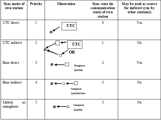
Note Class B (CSTDMA) AIS devices always transmits 11 - semaphore sync mode.
Determination of position accuracy information
| Accuracy status from RAIM (for 95% of position fixes)(1) | RAIM flag | Differential correction status(2) | Resulting value of PA flag |
|---|---|---|---|
| No RAIM process available | 0 | Uncorrected | 0 = low (>10 m) |
| EXPECTED RAIM error is < 10m | 1 | 1 = high (< 10m) | |
| EXPECTED RAIM error is > 10m | 1 | 0 = low (>10 m) | |
| No RAIM process available | 0 | Corrected | 1 = high (< 10m) |
| EXPECTED RAIM error is < 10m | 1 | 1 = high (< 10m) | |
| EXPECTED RAIM error is > 10m | 1 | 0 = low (>10 m) |
(1) The connected GNSS receiver indicates the availability of a RAIM process by a valid GBS sentence of IEC 61162; in this case the RAIM-flag should be set to "1". The threshold for evaluation of the RAIM information is 10 m. The RAIM expected error is calculated based on "expected error in latitude" and "expected error in longitude" using the following formula: 
(2) The quality indicator in the position sentences of IEC 61162 received from the connected GNSS receiver indicates the correction status.
(Source : International Telecommunications Union Recommendation ITU-R M.1371-5)
AIS Class A Ship Static and Voyage Related Data (Message 5)
In addition, the Class A AIS unit broadcasts the following information every 6 minutes. Should only be used by Class A shipborne and SAR aircraft AIS stations when reporting static or voyage related data:
| Parameter | Bits | Description |
|---|---|---|
| Message ID | 6 | Identifier for this Message |
| Repeat indicator | 2 | Used by the repeater to indicate how many times a message has been repeated. Refer to §?4.6.1, Annex 2; 0-3; 0 = default; 3 = do not repeat any more |
| User ID | 30 | MMSI number |
| AIS version indicator | 2 | 0 = station compliant with Recommendation ITU-R M.1371-1 1 = station compliant with Recommendation ITU-R M.1371-3 (or later) 2 = station compliant with Recommendation ITU-R M.1371-5 (or later) 3 = station compliant with future editions |
| IMO number | 30 | 0 = not available = default – Not applicable to SAR aircraft 0000000001-0000999999 not used 0001000000-0009999999 = valid IMO number; 0010000000-1073741823 = official flag state number. |
| Call sign | 42 | 7?=?6 bit ASCII characters, @@@@@@@ = not available = default Craft associated with a parent vessel, should use “A” followed by the last 6 digits of the MMSI of the parent vessel. Examples of these craft include towed vessels, rescue boats, tenders, lifeboats and liferafts. |
| Name | 120 | Maximum 20 characters 6 bit ASCII "@@@@@@@@@@@@@@@@@@@@" = not available = default The Name should be as shown on the station radio license. For SAR aircraft, it should be set to “SAR AIRCRAFT NNNNNNN” where NNNNNNN equals the aircraft registration number. |
| Type of ship and cargo type | 8 | 0 = not available or no ship = default 1-99 = as defined below 100-199 = reserved, for regional use 200-255 = reserved, for future use Not applicable to SAR aircraft |
| Overall dimension/ reference for position | 30 | Reference point for reported position. Also indicates the dimension of ship (m) (see below) For SAR aircraft, the use of this field may be decided by the responsible administration. If used it should indicate the maximum dimensions of the craft. As default should A = B = C = D be set to “0” |
| Type of electronic position fixing device | 4 | 0 = undefined (default) 1 = GPS 2 = GLONASS 3 = combined GPS/GLONASS 4 = Loran-C 5 = Chayka 6 = integrated navigation system 7 = surveyed 8 = Galileo, 9-14 = not used 15 = internal GNSS |
| ETA | 20 | Estimated time of arrival; MMDDHHMM UTC Bits 19-16: month; 1-12; 0 = not available = default Bits 15-11: day; 1-31; 0 = not available = default Bits 10-6: hour; 0-23; 24 = not available = default Bits 5-0: minute; 0-59; 60 = not available = default For SAR aircraft, the use of this field may be decided by the responsible administration |
| Maximum present static draught | 8 | In 1/10 m, 255 = draught 25.5 m or greater, 0 = not available = default; in accordance with IMO Resolution A.851 Not applicable to SAR aircraft, should be set to 0 |
| Destination | 120 | Maximum 20 characters using 6-bit ASCII; @@@@@@@@@@@@@@@@@@@@ = not available For SAR aircraft, the use of this field may be decided by the responsible administration |
| DTE | 1 | Data terminal equipment (DTE) ready (0 = available, 1 = not available = default) |
| Spare | 1 | Spare. Not used. Should be set to zero. Reserved for future use. |
| Number of bits | 424 | Occupies 2 slots |
Type of ship
Identifiers To Be Used By Ships To Report Their Type
| Identifier No. | Special craft |
|---|---|
| 50 | Pilot vessel |
| 51 | Search and rescue vessels |
| 52 | Tugs |
| 53 | Port tenders |
| 54 | Vessels with anti-pollution facilities or equipment |
| 55 | Law enforcement vessels |
| 56 | Spare - for assignments to local vessels |
| 57 | Spare - for assignments to local vessels |
| 58 | Medical transports (as defined in the 1949 Geneva Conventions and Additional Protocols) |
| 59 | Ships and aircraft of States not parties to an armed conflict |
Identifiers to be used by ships to report their type - other ships
| First digit(1) | Second digit(1) | First digit(1) | Second digit(1) |
|---|---|---|---|
| 1 - Reserved for future use | 0 - All ships of this type | - | 0 - Fishing |
| 2 - WIG | 1 - Carrying DG, HS, or MP, IMO hazard or pollutant category X | - | 1 - Towing |
| 3 - See right column | 2 - Carrying DG, HS, or MP, IMO hazard or pollutant category Y | 3 - Vessel | 2 - Towing and length of the tow exceeds 200 m or breadth exceeds 25 m |
| 4 - HSC | 3 - Carrying DG, HS, or MP, IMO hazard or pollutant category Z | - | 3 - Engaged in dredging or underwater operations |
| 5 - See above | 4 - Carrying DG, HS, or MP, IMO hazard or pollutant category OS | - | 4 - Engaged in diving operations |
| 5 - Reserved for future use | - | 5 - Engaged in military operations | |
| 6 - Passenger ships | 6 - Reserved for future use | - | 6 - Sailing |
| 7 - Cargo ships | 7 - Reserved for future use | - | 7 - Pleasure craft |
| 8 - Tanker(s) | 8 - Reserved for future use | - | 8 - Reserved for future use |
| 9 - Other types of ship | 9 - No additional information | - | 9 - Reserved for future use |
(1) The identifier should be constructed by selecting the appropriate first and second digits. The second digits 1, 2, 3 and 4 reflecting categories X, Y, Z and OS formerly were categories A, B, C and D.
Reference point for reported position and overall dimensions of ship
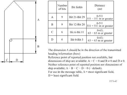
(Source: International Telecommunications Union Recommendation ITU-R M.1371-5)
External Position Fixing System (EPFS)
An EPFS can be any navigation system, receiver or integrated navigation system (INS), having an IEC 61162 interface. On a Safety of Life at Sea (SOLAS) Convention ship the navigation system must meet IMO performance standards and be certified. In practice most EPFS systems are currently GPS, and some GPS devices provide a dead reckoning (estimated position) mode. The type of EPFS used is derived from IEC 61162-1 sentences GLL, VTG, GDT, and ROT from the sensor input and is transmitted by the four bit Class A Message 5 or Class B Message 19. It is understood that the overwhelming majority of EPFS sensors interfaced with AIS are GPS. If an EPFS device is not connected to the AIS, the internal AIS GPS is used to provide position. The table describes fallback conditions and priority for how these positions sensors are used by AIS.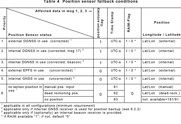
(Source International Electrotechnical Commission IEC 61993-2)
Long-range Automatic Identifcation System Broadcast Message (Message 27)
This message is primarily intended for long-range detection of AIS Class A and Class B “SO” equipped vessels (typically by satellite). This message has a similar content to Messages 1, 2 and 3, but the total number of bits has been compressed to allow for increased propagation delays associated with long-range detection. Note there is no time stamp in this message. The receiving system is expected to provide the time stamp when this message is received.
| Parameter | Bits | Description |
|---|---|---|
| Message ID | 6 | Identifier for this message; always 27 |
| Repeat indicator | 2 | Always 3 |
| User ID | 30 | MMSI number |
| Position accuracy | 1 | As defined for Message 1 |
| RAIM flag | 1 | As defined for Message 1 |
| Navigational status | 4 | As defined for Message 1 |
| Longitude | 18 | Longitude in 1/10 min (±180°, East = positive (as per 2’s complement), West = negative (as per 2’s complement) 181° (1A838h) = position older than 6 hours or not available = default) |
| Latitude | 17 | Latitude in 1/10 min (±90°, North = positive (as per 2’s complement), South = negative (as per 2’s complement) 91° (D548h) = position older than 6 hours or not available = default) |
| SOG | 6 | Knots (0-62); 63 = not available = default |
| COG | 9 | Degrees (0-359); 511 = not available = default |
| Position Latency | 1 | 0 = Reported position latency is less than 5 seconds; 1 = Reported position latency is greater than 5 seconds = default |
| Spare | 1 | Set to zero, to preserve byte boundaries |
| Total Number of bits | 96 |